Basic Crimping Instructions

Crimping is a termination method that firmly attaches a contact onto a wire by compressing the body of the contact around the wire using a crimping tool. The crimping process ensures metal-to-metal contact and establishes a reliable mechanical and electrical connection. Crimp termination is the preferred method for high-performance applications because it allows for higher contact densities, ease of installation, and increased reliability over solder termination. A crimp tool and the proper positioner are necessary for an effective and reliable crimp connection. A crimp tool can terminate a wide variety of contact sizes by simply changing the poistioner, making crimp termination a quick and easy task. Crimp contacts can also be removed and replaced if one becomes damaged without having to replace the entire connector.
The steps that follow will guide you through basic contact crimping. Before you begin, read through all of the instructions and gather all the necessary materials, including connectors, wires, contacts, connector accessories, crimper, dies, wire stripper/cutter, and ruler. Don’t forget to wear appropriate eye protection while you are working.
Step 1
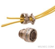
Slide the backshell and accessories over the wire bundle in their proper order. This must be done prior to crimping because the accessories cannot be placed on the cable once contacts are inserted into the connector.
Step 3
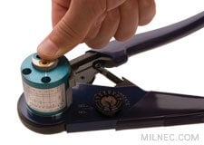
Adjust the crimper’s selector knob to the settings recommended on the positioner’s data plate that correspond to the contact size and wire gauge being used. When using a turret poistioner, be sure to press the turret into the positioner body until it locks into place after the appropriate contact size has been selected.
Step 5
Step 7
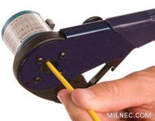
Insert the wired contact into the crimp tool. While holding the wire in place, squeeze the crimp tool handle. Once crimping has begun, the tool will not open until the crimping cycle is complete. When the tool handle has released, remove the wire and contact.
Step 9
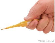
When crimping is complete, slide the wire and contact into the channel of the properly sized contact insertion tool. For double-sided plastic field installation tools, the colored tip is the insertion side, the white the removal side. Make sure that the tool tip lies flat against the contact shoulder.
Step 11
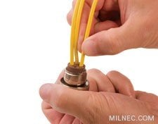
Remove the tool and pull back lightly on the wire to ensure that the contact is properly secured. Repeat the process with each remaining contact. For connectors with high contact densities, begin in the center cavity and work outward in a circular pattern.
Step 13
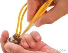
To remove a contact, place the wire attached to the contact to be removed in the proper extraction tool (white tip of plastic tool). Slowly slide the extraction tool down the wire and into the contact cavity until the tool tip bottoms against the contact shoulder.
Step 2
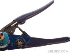
Select the proper crimp tool and positioner for the size of contact you are using. Open the crimp tool by squeezing the handles until the ratchet releases and the tool opens completely. Always adjust the tool in the open position to avoid damage.
Step 4
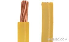
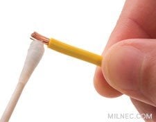
Make a clean cut at the end of the wire to be terminated and strip the insulation to the correct length. If stranded wire is being used, lightly twist the strands together. To find the proper strip length for your contact, see the Contact Specifications page of your connector series.
Step 6
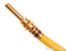
Insert the conductor into the crimp well until it rests on the bottom. Check the inspection hole to ensure that the conductor is visible. If wire jacket has been properly stripped, only a small amount of conductor should be visible between the top of the contact well and the wire jacket. When using stranded wire, ensure that all strands are contained.
Step 8
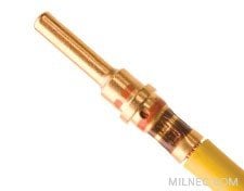
Inspect the crimped contact to ensure that all wire strands are contained in the crimp barrel and that the conductor is visible through the contact’s inspection hole. If no conductor is visible, re-crimping is recommended.
Step 10
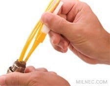
Hold the contact and tool perpendicular to the rear face of the connector insert. Push the contact into the insulator with firm and even pressure until the contact clicks into place.
Step 12
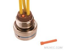
Check the mating face of the connector to ensure that all contacts are fully inserted. If not, completely remove the partially inserted contacts using the proper extraction tool and insert again. Fill all unused cavities with sealing plugs to environmentally seal the connector face. Sealing plugs should be inserted head first until fully seated.
Step 14
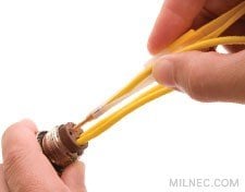
Hold the wire firmly in the tool and carefully pull back to extract the tool and the contact from the connector simultaneously. Repeat the process for all contacts to be extracted.


